

3D Printing Rocks
I decided that, rather than do yet more simulation, I'd start trying to prototype my gates.
The simplest way to do this seemed to be designing them in some CAD tool and having a 3D print done. I spent a number of weekends going through Blender tutorials, only to figure out that it just wasn't the right tool for the job. It's much more aimed at making cool pictures and animations, and not so good for constraints like "all walls must be at least 2mm thick". After getting stumped there and working on other things for a while, some friends turned me on to OpenSCAD. I'd just like to give a big shout out to Clifford Wolf, the author--it's a great tool, and I had my first design in about 1 day of work. I tweaked it a bit more before I had the prints done, but still, it was really fast to work with.
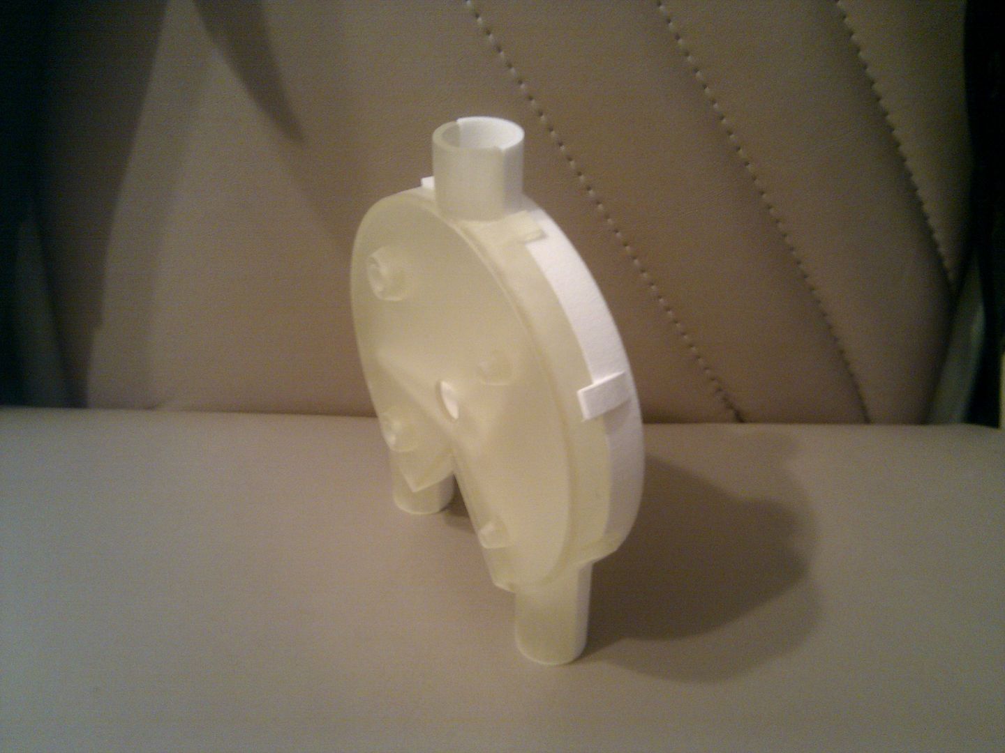
Here are a couple of shots of the gate I printed; I got one side in transparent plastic so that I could see what was going on inside, but I got the rest in white because it was much cheaper. Big thanks to shapeways.com for getting me my parts in 9 days, upload-to-delivery, for half the price that I could have gotten it done in the U.S.
Here's the fully-assembled gate, lacking only the metal axle, a 3/8" D-profile steel shaft. The shaft's way bigger and heavier than I wanted, but apparently it's hard to find small, light shafts with that profile.
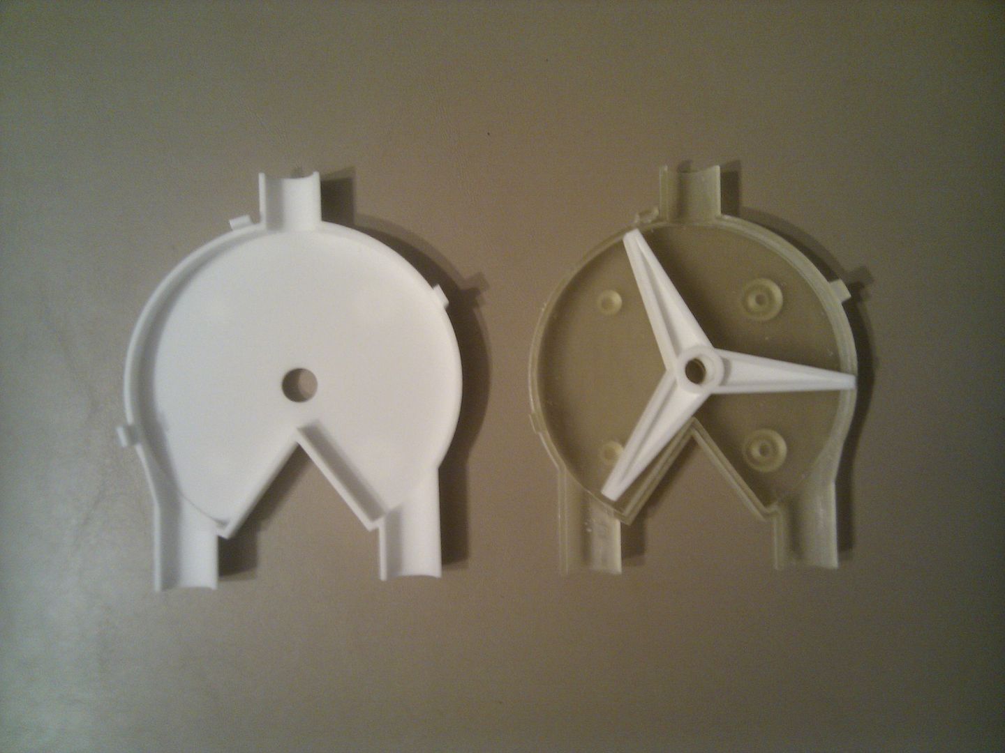
Here are the 3 parts laid out so that you can see inside. Those circles and doughnuts on the transparent gate are actually on the far side; they're alignment pegs and sockets, and the white one has them too. They're so that you can slap a whole stack of these gates together without worrying about binding on the axle.
I've already designed the next generation, about 2/3 the size and with a very different axle that I hope will reduce friction quite a bit. I also picked up some tungsten carbide bearings to replace the steel ones I started with--doubling gravity may be cheating, but if it works, I'm for it.
posted by Eric Uhrhane @ 7:02 PM
![]()
![]()
5 Comments:
I just found your blog, searching for mechanical logic gates. I also had the idea to build a device that used rolling balls or marbles to calculate. My first thought was to build a mechanical tic-tac-toe game, with the idea that eventually a general-purpose machine could be built using the same principles. Your design work and the time it has taken (5+ yrs) make it plain that this is not something whipped up in a couple of evenings.
I am curious to know what the status of the project is, and I will be checking back for updates.
I'm afraid I have no recent progress to report. I've done 2 generations of prototypes [the ones shown here and a smaller, more efficient set], but now I need to work on figuring out the right curvature for the gates' interior surfaces. I want balls to go flying through without slowing down if they're not actually toggling the state.
Incidentally, the second-generation gates seem like they're going to give me all the drive strength I was hoping for--I think a single tungsten carbide ball will be able to flip at least 18 connected gates, which means that I can switch large buses efficiently, and don't have to split up the designs much. I was really worried about that; if I couldn't at least switch 10 gates at once, the design would have gotten really ugly.
Feb 15, 2015
I am back, lurking on your blog again. Like you, I pick up my own plans for a mechanical ball-driven computer after months (or years) of mental neglect. I am returning to this with the idea to build a series of logic gates with my son as a science fair project. No more model volcanos or solar cars for us!
My question this time is about the physical gates themselves. What size were the gates and the metal balls you planned to use? Do you still have the design files to print the gates?
I could do some testing on my own, but why make my own mistakes in prototyping when I might be able to learn from the successes of someone else.
Thank you for any help you may be able to provide.
Kevin
I'd have to dig to find the exact dimensions, but IIRC the tungsten carbide BBs were about 0.25" or so, with the smaller gate print then being about 2" across.
I can't remember what I used to do the gate design. It was either OpenSCAD or my own expanded clone of it. If it's the former, I can send you the files. If it's the latter, the syntax is almost the same [it's javascript that looks quite similar] so you could probably back-port it if you wanted to.
However, if you just want to do something simple like a full adder, you could make gates a lot cheaper out of balsa wood. I can't find the link right now, but I'm sure I've seen a video of one using ping pong balls like this: http://helge.ru-stad.name/ppb_comp/ppbcne.htm
Give me your email address if you want the files, and I'll try to dig them up.
Thank you for the information, that will help. My son and I are looking at getting a 3-D printer of our own, but until we do, I will be working to make prototypes out of wood.
First step is making NOT-AND-OR gates as an example of basic Boolean logic operations, maybe a latched bit of memory. I am thinking of implementing 2 or 3 opcodes like load-add-subtract to keep the circuit simple enough to actually build.
There is a talented wood worker, Matthias Wandel, who built a 6-bit adder for marbles. Check out http://woodgears.ca/marbleadd/index.html.
If my son and I accomplish anything of note, we will be sure to document it and share it. Thanks again.
Post a Comment
<< Home